The RLN4008B Parts List
|
Reference
Symbol |
Description |
| CAPACITOR |
C1, C3, C4 |
10uF 25V |
| |
C2 |
1uF 50V |
| |
C5 |
220pF |
| DIODE |
CR1, CR2, CR7 thru CR10 |
1N4001 |
| |
CR3 thru CR6 |
Zener 7.5V , 1/2W |
| |
DS1 |
LED red , low current |
| JACK |
J1 |
Receptacle Power |
| |
P2 |
25 Position Male "D" |
| |
P4 |
15 Position Male "D" |
| TRANSISTOR |
Q1 thru Q3, Q5, Q7 |
NPN 2N3904 |
| |
Q4, Q6 |
PNP 2N3906 |
| RESISTOR |
R1, R3, R4, R7, R9, R10, |
4k7 1/4W |
| |
R12, R13, R15, R16, R17 |
4k7 1/4W |
| |
R2, R8 |
20k 1/4W |
| |
R5 |
3k 1/4W |
| |
R6 |
1k5 1/4W |
| |
R11, R14 |
2k 1/4W |
| |
R18 |
3k9 1/4W |
| SWITCH |
SW1 |
Toggle, SPST |
| IC |
U001 |
78L05 Voltage Reg. |
| |
U002 |
ICL7660 Inverter |
| |
U003 |
CA3140E |
| OTHER |
BT1 |
Battery 9V |
| HARDWARE |
PCB Mounting |
7 mm Round Spacer 4 pcs |
| |
Screw , PCB to Spacer |
M3 x
4 4 pcs |
| |
Screw , Chassis to Spacer |
M3 x
6 4 pcs |
| |
Plastic Chassis |
W75 x L103 ( min. inside
dim.) |
A modification
you may be interested in for the RIB. There have been reports of problems
using the RIB on different computers. It looks like one of the problems
might be a lack of negative voltage swing on the Busy out and RX (data
out) lines back to the computer. You might want to try and change the
value of R14 to 1.5k and R11 to 1K.


** click image to enlarge
**
Final Release
The PCB size is
75 mm x 103 mm. Single sided , which is suitable for
homebrew.
On board 9 volt
battery compartment and DC Power Jack are provided.
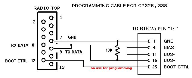
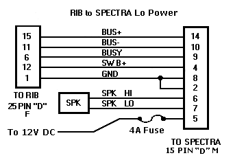
The RIB card is
used to connect up most later model Motorola Radios to the PC for
programming.
The Connection
from the PC's COM port uses a DB9 / DB25 Connector to
DB15 on RIB card.
The output from
the card can go to any standard motorola DB25 Cable that
support this interface connector.
If you want to built the RIB with
this PCB , take your own risk . |