International Conference on Robotics Vision and Parallel Processing for
Industrial Automation (ROVPIA '96)
November 28-30, 1996, Ipoh, Perak, Malaysia
INTERACTIVE ASSEMBLY MODELLING WITHIN A VIRTUAL ENVIRONMENT
Mud-Armeen Munlin
Computer Technology Laboratory (CTL)
National Electronics and Computer Technology Center (NECTEC)
108 Bangkok Thai Tower, Rangnam Road
Rajthevi, Bangkok 10400, Thailand
E-mail:
amin@ctl77.nectec.or.th
Abstract
This paper presents research into interactive constraint-based assembly
modelling using an intuitive 3D graphical interface.
The approach is to integrate
3D interactive graphical techniques and 3D constraints. This
provides the user with an advanced interactive environment
to perform assembly modelling, purely by direct manipulation.
An automatic constraint recognition technique has been developed
to recognise assembly mating conditions
purely from the user's 3D manipulations.
A large set of constraints such as
against, cylindrical fit, gear contact, rack-pinion contact, screw fit
and spherical fit can be automatically recognised
by this technique.
Constraints recognised from the user's 3D manipulations
are maintained in a Relationship Graph (RG).
The RG maintains the constraint dependency to support
the constraint propagation to the relevant geometric entities.
This frees the user from having to maintain the constraint consistency
when the constraints are added or modified and also
ensures the interactive response to 3D manipulations of the geometry.
A technique referred to as allowable motion is used to
satisfy 3D constraints. This technique
uses the degrees of freedom of objects to derive
transformation operations to satisfy a constraint.
It is also used to achieve the accurate 3D positioning of a solid model
by automatically constraining its 3D manipulations.
The graph-based algorithms reported in this work support
interactive dragging of under-constrained models.
This allows the simulation of the `kinematic' behaviour of an assembly
in response to 3D manipulation.
These algorithms support the forward and backward
propagation of constraints to simulate the realistic
manipulation of assembly models within the virtual environment.
Keywords:
Advanced 3D Interaction Techniques, 3D Constraint, Virtual Environments,
Assembly Modelling, Allowable Motion, Kinematic Simulation.
1. Introduction
The recent advent of Virtual Environment (VE) technology
has made it feasible to directly interact with
objects in 3D space.
This offers the potential
to develop highly interactive 3D user interfaces
for a variety of engineering applications such as virtual manufacturing
[6] and assembly modelling [5].
A number of commercial and non-commercial VE toolkits are
currently available to support the development of virtual environments for
these applications. However, a common weakness of the
existing virtual environments is the lack of efficient geometric
constraint management facilities. As a result, it is difficult
to achieve the accurate 3D positioning of solid models
using 3D input devices.
Another problem with assembly modelling application is that most of
the current systems
employ the menu interaction in order to support the process.
This results in a tedious and often non-intuitive process
which means that a lot of menu interactions are required to
manipulate a complex assembly.
The interactive constraint-based solid modelling approach
reported in [1] overcomes this problem
by enabling the user to directly interact graphically with the
assembly without the use of menus. The purpose of this paper is to
extend this approach to realistic engineering assemblies. It will
be shown that combination of high performance graphics systems
and management of 3D constraints within the virtual
environment provides a new and powerful tool for
modelling assemblies.
2. Interactive Constraint-Based Assembly Modelling
An Interactive Constraint-Based Solid Modelling (ICBSM) [1] was originally
developed in the School of Computer Studies, The University of Leeds.
The primary contribution of this work was the development of a number
of new 3D interaction techniques which integrate 3D constraints and
direct 3D manipulation techniques.
These 3D interaction techniques are
automatic constraint recognition
and allowable motion.
The initial results of the work have been reported in [1, 2].
The author has evaluated this system against several mechanical industrial
case studies e.g. a puma robot, a diaphragm valve,
and a shaft mounted speed reducer.
The evaluation has demonstrated that these 3D
interaction techniques
has the potential development to support mechanical CAD/CAM systems,
i.e. design and kinematic analysis of mechanical assemblies.
However, before this potential can be fully exploited, the techniques
for supporting the complex
constraints such as screw fit, gear contact,
and rack-pinion contact [3] need to be developed.
In addition, graph based algorithms for kinematic simulation
also need to be studied.
This has led to development of Interactive Constraint-Based Assembly Modelling
(ICBAM).
2.1 Automatic Constraint Recognition
The automatic constraint recognition process is used to
identify constraints purely from 3D manipulation of the target
solid model (Tar-SM). These constraints will then be represented
in the relationship graph (RG).
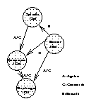
The RG (see Figure 1)
is a directed graph where each node corresponds to
an assembly component.
Every arc of the RG corresponds to a constraint
between two components. The direction of the arc denotes
the dependency between two components.
The component which the arc points to, depends on the component
which the arc departs from. This implies that the changes
in the 3D location of the latter are always propagated to the former.
Figure 1. The relationship graph of diaphragm valve assembly
When a new constraint is recognised,
a visual feedback is provided to the user by
highlighting the relevant geometric elements.
If the user continues to move the Tar-SM,
the newly identified constraint
is ignored and the constraint recognition process is continued.
On the other hand, if the user does not move the Tar-SM
within a prescribed time, the constraint
is inserted into the RG.
Each constraint also has its own allowable motion which is used to
automatically derived the motion variable, number of degrees of freedom,
and relative motion. This allowable motion is also used for
determining the resultant relative motion of the component
if several constraints are imposed on it.
In this work, a set of complex constraints such as
screw fit, gear contact
and rack-pinion contact have been implemented.
A set of simple constraints such as against, cylindrical fit,
spherical fit, concentric, parallel, coincident, etc.,
have already been defined
in [4, 1].
2.2 Allowable Motion
The term allowable motion refers to the remaining
degrees of freedom for an under-constrained solid model or geometric element.
Allowable motions of a solid model is used as
a means of automatically constraining 3D manipulations of the solid model
without invalidating its existing constraints. This results in
an intuitive way of achieving the accurate 3D positioning of the
solid model simply through 3D manipulation.
Allowable motion technique is also used to provide an efficient means of
satisfying a constraint by applying a number
of transformation operations to the solid model.
A number of allowable motion types have been developed (see [1]).
Only the following two new types which are associated with the complex
constraints are discussed.
- Coupled Translation and Rotation: associated with screw fit
and rack-pinion contact.
- Coupled Rotation and Rotation: associated with gear contact.
2.2.1 Coupled Translation and Rotation
This refers to a case where the allowable translation of the Tar-SM
is coupling with its allowable rotation or with the allowable rotation
of its mating component.
For example, a screw fit restricts
the motion between a screw and a nut to a combined rotation
and translation along a common axis. The translation is a function of
rotation (Theta) and screw pitch as described below [3] (see Figure 2).

Figure 2. Coupled Translation and Rotation
| translation(Theta) = pitch * (Theta)/(2*pi) |
where (Theta) is the actual rotation, and pitch is the screw pitch.
Similarly, the allowable motion
for the rack-pinion can also be specified as a coupled
translation and rotation.
In this case, the allowable translation of the Tar-SM
is converted into the allowable rotation of its mating component,
e.g. a mating gear teeth of the rack and pinion [3] (see Figure 2).
The final motion will be
the translation along the rack axis and the rotation about a
pinion's axis. The rotation part shall be calculated from:
| (Theta) = translation/pinion_radius |
where (Theta) is the actual rotation,
translation is the actual displacement,
and pinion_radius is the radius of the pinion.
2.2.2 Coupled Rotation and Rotation
This refers to a case where the allowable rotation of the Tar-SM
is converted into the allowable rotation of its mating component.
For example, a mating gear teeth and
a mating cam and follower. In the case of mating gear teeth, the rotary
motion of the driver and the follower gears can be written in term
of the speed ratio (omega), where this speed ratio must remained
constant in order to prevent any impact and vibration even at low
speed. At any instance the motion of the follower gear may be considered
as a rotation about its axis where the direction is opposite to the driver
gear axis while maintaining the tangent constraint (see Figure 3).
The actual rotation of the follower gear
shall be calculated from:
| (Theta_F) = (Theta_D) * (T_D/T_F) |
where T is the the number of gear teeth, and
(Theta) is the actual rotation of the gear.
F and D denote the follower and the driver gear respectively.
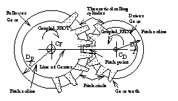
Figure 3. Coupled Rotation and Rotation
3. Graph-based Algorithms for Kinematic Simulation
This section presents a new graph-based algorithm that can efficiently
perform a two-way propagation (i.e. forward and backward in the
directed RG) of the user's 3D manipulations among constrained objects.
The significant feature of this algorithm is its ability to ensure
interactive response to 3D manipulations by exploiting the
allowable motion techniques and the directed nature of the RG.
This algorithm is also used for simulating the kinematic
behaviour of an assembly in response to user's 3D manipulation.
For example, consider a diaphragm valve assembly and its RG
in Figure 1,
while the user is rotating the spindle of the
diaphragm valve, the compressor, and the diaphragm should
be transformed according to their allowable motions, thereby
allowing the diaphragm
to move up/down in order to turn on/off the valve bore, respectively.
3.1 Forward Propagation
This is concerned with propagating the user's 3D manipulations of the
Tar-SM to its children so as
to maintain their associated constraints as valid. To achieve this,
a particular propagation sequence is derived that ensures each object
to be processed before its dependent children. This sequence
also avoids repeatedly updating the same object.
It is obtained in two steps:
- Order the graph nodes through the breadth-first traversal of
the RG, starting from the node of the Tar-SM, and
also mark each encountered arc;
- Remove repeated graph nodes in a reverse order (i.e. starting
from the end to the beginning of the order).
From the RG in Figure 1, the propagation sequence is derived as
follows: start with the node Sp, perform a breadth-first traversal
on the RG. This results in the order: Sp-Co-Di ; there is no repeated
node in this case. The final order is Sp-Co-Di.
Following the propagation sequence, the changes in the 3D location of the
Tar-SM are then propagated to each dependent object simply by
transforming it in the same amount as the 3D location of the Tar-SM
is updated, i.e., transforming the Tar-SM and all its dependent objects
together.
3.2 Backward Propagation
This is concerned with propagating the user's 3D manipulations of the
Tar-SM to its parents.
Backward propagation is required if the forward propagation can not
be initialised from the Tar-SM. The propagation sequence is derived
by selecting one of its parent RG nodes whose allowable motion
is available to absorb the 3D manipulation of
the Tar-SM. This is done as below:
- order the graph nodes through the breadth-first traversal
of the RG by following the arcs of each node in a
reversed direction, starting from the node
of the Tar-SM;
- remove repeated graph nodes in a reversed order (i.e.
starting from the end to the beginning of the order);
- check each node from the beginning of the order until a node
(i.e. its parent) is found whose allowable motions
are available to absorb the 3D manipulation.
In the previous example (see Figure 1),
consider the graph containing the
nodes Bo, Sp, Co and Di.
Suppose the user translates the compressor, this translation
cannot be absorbed by the compressor (the allowable
motion of the compressor is
non-translation and rotation about line).
Therefore, the backward propagation is invoked in order to find the
constraining object that can absorb this translation. The propagation sequence
may be obtained as follows: start with the node Co, perform a
breadth-first traversal of the RG in a reversed direction. This
results in the order: Sp-Bo-Bo; remove repeated nodes from the end
to the beginning. the final order is Sp-Bo. According to this
order, the node Bo is selected, since it has a free allowable motion.
The translation will then be propagated from the node Bo to
all its dependent objects.
4. Implementation and Results
A system has been implemented in C, based on the
techniques described in this paper.
This system runs on SGI workstations such as Indigo, Indy, and Indigo2.
The visualisation of the virtual environment
is supported by the IRIS Inventor.
The system enables the user to carry out
interactive assembly and dis-assembly operations simply by 3D manipulations
in a realistic manner as she does in the physical world.
Currently, the system supports a rich set of
3D constraints such as against, concentricity, cylindrical fit,
spherical fit, screw fit, rack-pinion contact and gear contact.
A number of case studies have been conducted on the system
to successfully demonstrate the feasibility of the techniques.
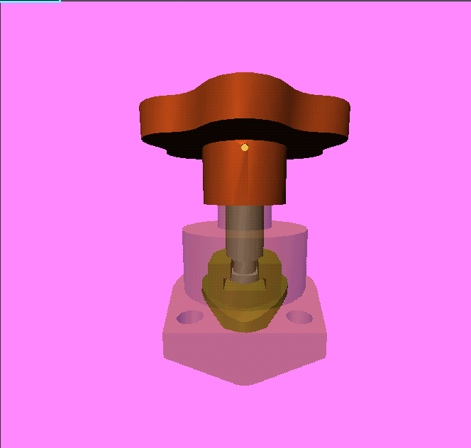
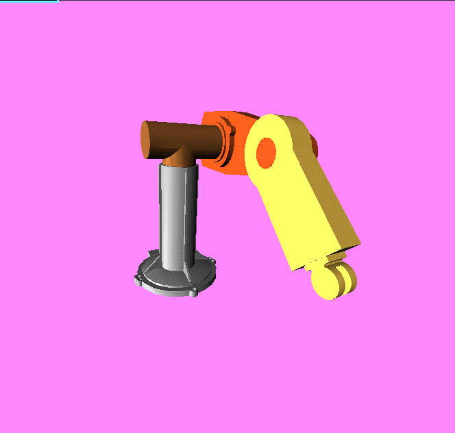
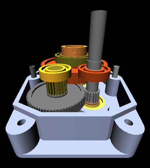
These case studies are a Puma Robot, a Diaphragm Valve
and a shaft mounted speed reducer as shown in Figure 4.
Figure 4. Results of the case studies
5. Conclusions and Future Work
This paper has presented 3D interaction and constraint techniques
which make it possible to support interactive assembly
and dis-assembly operations simply by 3D manipulations.
Importantly, these techniques allow the kinematic behaviours
of under-constrained models to be interactively simulated by
3D interaction. Such techniques are essential for exploiting VE technology
in engineering applications such as solid modelling and assembly modelling.
Future research is under way at NECTEC
to exploit the work described in this paper in collaboration
with MAnufacturing Technology supported by advanced and
integrated Information system through international Cooperation (MATIC)
project to carry out the research on Manufacturing Automation in Thailand.
These activities encompass a number of
research areas described in CTL's white paper [6].
Typical research efforts are in the areas of CAD/CAM/CAE, Rapid Product
Development, Integrated Product Development, and Tele-manufacturing.
References
[1] M. Fa, T. Fernando, and P.M. Dew. Interactive Constraint-based Solid
Modelling using Allowable Motion. Proc. of ACM/SIGGRAPH Symposium on Solid
Modelling and Applications, pages 243-252, May 1993.
[2] T. Fernando, M. Fa, P.M. Dew, and Mudarmeen Munlin. Constraint-based #D
Manipulation Techniques for Virtual Environments. In Virtual Reality
Applications, Ed. by R.A. Earnshaw, J. Vince, and H. Jones, 1995.
[3] ISO. Industrial Automation Systems and Integration - Product Data
Representation and Exchange - Part 105: Integrated Application Resources:
Kinematics. December 1993.
[4] S.H. Mullins and D.C. Anderson. A Positioning Algorithm for Mechanical
Assemblies with Closed Kinematic Chains in Three Dimensions. In Proc. Symp.
Solid Modelling and Applications, pages 271-282, ACM Press, New York, 1993.
[5] R. Sodhi and J.U. Turner. Towards modelling of assemblies for product
design. CAD, 26(2): 85-97, February 1994.
[6] Peraphon Sophatsathit. Globalized Virtual Manufacturing. Technical Report,
National Electronics and Computer Technology Center (to be appeared in
CALS-Singapore '96), November 1996.
